


Bubble tracking in gravity casting gating system
2025-03-08
Efficient Deburring and Grinding Method for Die-cast Aluminum Auto Parts
2025-03-19Causes of shrinkage and shrinkage holes in ductile iron castings covered with sand and their improvement process
summary:
- According to the solidification characteristics of ductile iron and its volume change during the solidification process, the viewpoint that the iron mold sand-coated casting process for producing ductile iron parts also needs shrinkage compensation is proposed. In the process design, the good rigidity of the iron mold casting should be fully utilized to more effectively exert the self-shrinkage compensation characteristics of the graphitization expansion of ductile iron. The riser-free method, sequential solidification method, direct practical riser method, balanced solidification method, cold riser method, chilling method and numerical simulation technology are respectively adopted, and the process measures to prevent shrinkage and shrinkage cavities in castings are elaborated in detail with several examples.
Ductile iron has the advantages of high strength, good toughness and low cost, and is widely used in important manufacturing industries such as automobiles, agricultural machinery, ships, pipelines, hydraulic machinery, etc. However, the shrinkage and shrinkage defects of ductile iron parts have always been a prominent problem in production. Iron mold sand casting is a new casting technology developed on the basis of metal mold casting and shell mold casting.
Since the mold composed of the iron mold and the sand coating has good rigidity, fast cooling, and good density of the sand coating, the castings produced have the advantages of high dimensional accuracy, small processing allowance, good surface quality, dense internal structure, and good product quality consistency. Especially for ductile iron parts, the graphitization expansion can be fully utilized to give play to its self-shrinkage characteristics. However, this does not mean that ductile iron parts cast by iron mold sand coating will not have shrinkage defects, and can be cast without risers. Based on the solidification characteristics of ductile iron, this paper combines numerical simulation technology to introduce various methods and successful cases of preventing shrinkage holes and shrinkage in iron mold sand coating casting process.
ONE
Domestic and foreign foundry workers have conducted decades of research on ductile iron and have found that it has different solidification characteristics from other alloys, which are mainly manifested in the following aspects:
(1) The eutectic solidification range of ductile iron is relatively wide. When eutectic crystallization of ductile iron occurs, the graphite core is surrounded by austenite when it grows to a certain size in the liquid phase as a result of magnesium addition. Since the austenite shell hinders the diffusion of carbon atoms from the molten liquid to the graphite spheres, the growth rate of the graphite spheres slows down, and the solidification process proceeds slowly, so that a new graphite nucleus is formed on the new graphite heterogeneous core at a greater degree of undercooling to maintain the eutectic solidification. Therefore, the eutectic transformation occurs in a relatively wide temperature range, resulting in the coexistence of solid and liquid phases on a wide section of the casting, solidification in a mushy state, making it difficult to compensate for shrinkage during solidification.
(2) Ductile iron has many graphite cores. Compared with gray cast iron, ductile iron has to go through spheroidization and inoculation treatment. It has much more graphite cores than gray cast iron, and the size of the eutectic clusters is much finer than that of gray cast iron.
(3) Ductile iron has a large graphitization expansion force during solidification. During the eutectic solidification process, the graphite of ductile iron is quickly surrounded by an austenite shell. The expansion caused by the growth of graphite cannot be transmitted to the molten iron, resulting in a larger eutectic expansion force. The graphitization expansion force is 5 times that of gray cast iron. If the rigidity of the mold is not high, it will cause the mold to expand and the shape of the casting to expand. The graphitization expansion force is released, reducing the shrinkage compensation effect on the metal during solidification and shrinkage, thereby increasing the shrinkage cavity and shrinkage tendency.
(4) The volume change pattern of ductile iron solidification process is divided into three stages: liquid contraction from the time the molten iron is filled to the eutectic temperature; volume expansion caused by the precipitation of graphite nodules during the eutectic solidification process; volume contraction during the cooling process after the molten iron solidifies.
Domestic and foreign experts have proposed many calculation methods for the volume change of ductile iron during solidification. Zhou Gen, a senior engineer at FAW Xichai, proposed a new calculation method based on the previous calculation methods: for cast iron with a w (Si) content of 2.5%, the w (C) content of eutectic austenite is 1.54%~1.6%; if the molten iron contains 3.8% C and 2.5% Si, the amount of graphite precipitation is 3.8%-(1.54~1.6)%=(2.2~2.26)%, and the expansion is 4.4%~4.52% (the volume expansion of each 1% of graphite precipitation is 2.02%≈2%). The pouring temperature is 1 350℃, the eutectic temperature is 1 150℃, the temperature drop of 50℃ in the pouring system is removed, the superheat is 150℃, and the liquid shrinkage is calculated according to the liquid shrinkage rate (1.6~1.8)%/100℃, the liquid shrinkage is 2.4%~2.7%, and the metal solidification shrinkage is calculated according to the data of 3% for non-graphitized steel, then the total shrinkage is 5.4%~5.7%. If the pouring temperature is higher, the total shrinkage will be greater, which obviously cannot be completely offset by the graphitization expansion. Therefore, no matter what process is used, ductile iron parts always need to be compensated for shrinkage. As long as the mold rigidity is sufficient, the view that ductile iron will not shrink is wrong, and the iron mold sand casting process is no exception.
TWO
Casting CAE technology uses computers and related software to numerically simulate the filling and solidification process of castings, and processes and analyzes the obtained data to predict defects and optimize the process.
Filling simulation simulates the influence of the flow process of molten metal in the casting mold on the forming of castings. The smooth flow of molten metal and the reasonable filling sequence are important conditions to ensure the quality of castings, and are also the prerequisites for a reasonable solidification sequence. Through filling simulation, the flow state of molten metal in the pouring and riser system can be analyzed, the pouring and riser system can be optimized, the flow separation of molten metal can be avoided, and the flushing and erosion of the model by molten metal can be reduced. The solidification process is the process of transformation from liquid to solid after the molten metal fills the cavity. Through solidification simulation, the solidification sequence of molten metal in the casting can be analyzed, and the defects occurring during the solidification process can be predicted.
At present, numerical simulation technology has been widely used in casting process design. The heat transfer process of the iron mold sand-coated casting process is relatively complex compared to the general sand casting process, including the heat transfer between "casting-sand coating-iron mold-atmosphere". After verification through experiments and production practice, the simulation analysis of this process is also relatively mature and reliable.
THREE
The two main characteristics of the iron mold sand coating casting process are: ① good mold rigidity; ② adjusting the thickness of the sand coating layer in each part of the mold can improve the cooling rate of each part to a certain extent. Therefore, its advantages should be fully utilized in process design. For ductile iron parts, the good mold rigidity can more effectively exert its self-compensation characteristics of graphitization expansion. It is generally believed that under the premise that no graphite floating occurs and no primary graphite precipitation occurs, the higher the amount of w (C) and w (Si), the stronger the inoculation effect, the more conducive to graphitization, and the greater the graphitization expansion, the better the self-compensation effect.
However, as mentioned above, no matter how good the mold rigidity is, ductile iron parts always need to be compensated. In the iron mold sand coating process, there are several methods to prevent shrinkage cavities and shrinkage of castings, and they are explained with examples.
3.1 No-riser method
The riserless method is to use the pouring system to carry out liquid shrinkage compensation, and maximize the use of graphitization expansion to complete self-shrinkage compensation. The iron mold sand coating process was first successfully applied to the production of crankshafts, and the riserless casting of crankshafts is also the most typical. Its process feature is the use of a thick pouring system to provide liquid shrinkage compensation for the casting. The riserless method is suitable for ductile iron castings with a casting modulus of >2.5 cm. It requires high metallurgical quality of molten iron, a small flat and thin ingating channel, and the introduction of molten iron at multiple points. In the absence of cold shut of the casting, the pouring temperature should be low.
Figure 1 shows the liquid phase area of the Steyr 615 crankshaft when it solidifies 30% after pouring. It can be seen from the figure that in the early stage of solidification, the ingating channel on the crankshaft fan plate has been closed, and the center of the main journal and the connecting rod journal has formed an overall thick liquid phase area. In the later stage, self-shrinkage compensation is completely achieved by graphitization expansion.
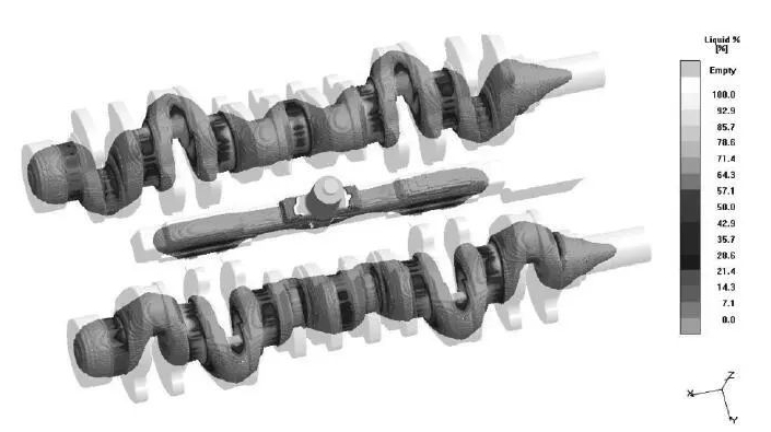
Figure 1 Liquid phase display when the casting solidifies 30%
3.2 Sequential solidification method
The riserless method is to use the pouring system to carry out liquid shrinkage compensation, and maximize the use of graphitization expansion to complete self-shrinkage compensation. The iron mold sand coating process was first successfully applied to the production of crankshafts, and the riserless casting of crankshafts is also the most typical. Its process feature is the use of a thick pouring system to provide liquid shrinkage compensation for the casting. The riserless method is suitable for ductile iron castings with a casting modulus of >2.5 cm. It requires high metallurgical quality of molten iron, a small flat and thin ingating channel, and the introduction of molten iron at multiple points. In the absence of cold shut of the casting, the pouring temperature should be low.
Figure 1 shows the liquid phase area of the Steyr 615 crankshaft when it solidifies 30% after pouring. It can be seen from the figure that in the early stage of solidification, the ingating channel on the crankshaft fan plate has been closed, and the center of the main journal and the connecting rod journal has formed an overall thick liquid phase area. In the later stage, self-shrinkage compensation is completely achieved by graphitization expansion.
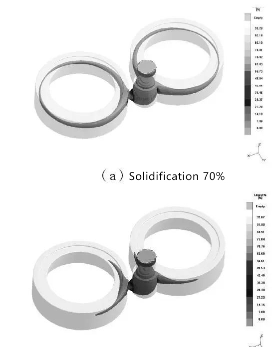
Figure 2 Traction sheave solidification process
3.3 Direct practical riser method
The direct practical riser method uses a riser to compensate for the liquid shrinkage of the casting. When the liquid shrinkage stops or the volume expansion begins, the riser neck or the inner gate solidifies in time, so that the eutectic expansion in the casting mold puts the molten metal under positive pressure to prevent vacuum inside the casting. The direct practical riser is suitable for ductile iron castings with a casting modulus <2.5 cm. The casting process has a high yield rate and the riser is easy to remove.
The bearing cover weighs 3.6 kg per piece, with an outline size of 118 mm×110 mm×60 mm. The material is QT500-7. When the iron mold sand casting process is used, 14 pieces are arranged in one mold. The casting is liquid-compensated using a direct practical riser. Figure 3 shows the liquid phase area when the bearing cover is 60% solidified after pouring. As can be seen from the figure, the riser neck has solidified at this time, and the liquid metal in the casting and the riser has been disconnected. The yield rate of this process reaches 76.5%, which is 25% higher than the yield rate of clay sand casting (51.5%).
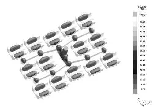
Figure 3: Liquid phase display when the casting solidifies 60%
3.4 Equilibrium solidification method
The balanced solidification theory believes that the role of the riser in cast iron is only to compensate for the difference in expansion and contraction caused by the cooling and solidification of the casting. The riser does not have to solidify later than the casting. The core is: the riser should be both away from the hot spot and close to the hot spot to reduce the thermal interference of the riser on the casting and facilitate shrinkage compensation.
The rotor material is QT500-7, the casting is 628mm long, 195mm wide, and the diameter of the middle cylinder is 65 mm. The middle cylinder intersects with the two side plates to form a hot spot. The balanced solidification method is adopted to set the riser on the side of the truncated cone next to the hot spot, and the flat inner runner is facing the inner diameter of the cylinder to avoid the molten iron directly filling the hot spot. Figure 4 shows the liquid phase area of the rotor casting when it solidifies 85% after pouring. It can be seen from the figure that an isolated liquid phase area is about to form at the hot spot of the middle cylinder. The volume shrinkage of this liquid phase area is offset by graphitization expansion in the later solidification process.
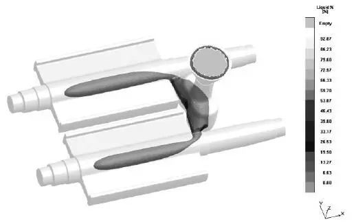
Figure 4 shows the liquid phase when the casting solidifies 85%
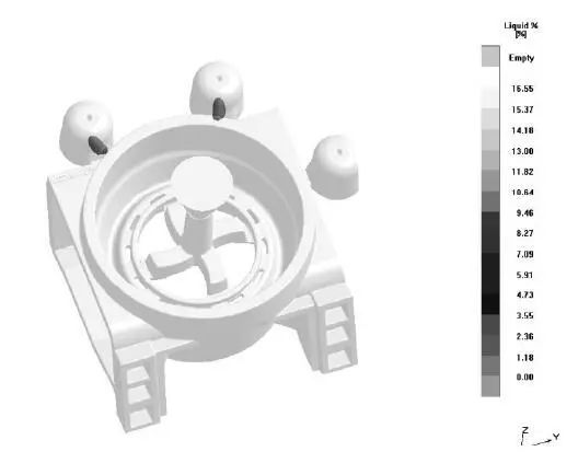
Figure 5 Liquid phase display when the casting solidifies 97%
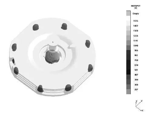
Figure 6 Hot section display
Figure 7 Process design of motor end cover
FOUR
(1) The iron mold sand-coated casting has good mold rigidity, fast cooling, and good density of the sand coating. When producing ductile iron parts, the graphitization expansion can be fully utilized to exert its self-compensation characteristics. However, according to the solidification characteristics of ductile iron and the volume change during the solidification process, it is concluded that the iron mold sand-coated casting process also needs to compensate for the shrinkage of ductile iron parts.
(2) Compared with the general sand casting process, the heat transfer process of the iron mold sand-coated casting process is relatively complex, including the heat transfer between "casting-sand coating-iron mold-atmosphere". After verification by experiments and production practice, the simulation analysis of this process is relatively mature and reliable.
(3) The iron mold has good mold rigidity and can effectively exert its self-compensation characteristics of graphitization expansion. Under the premise that no graphite floating occurs and no primary graphite precipitation occurs, the higher the C and Si content, the stronger the inoculation effect and the better the effect.
(4) The successful cases of using various methods such as riser-free method, sequential solidification method, direct practical riser method, balanced solidification method, cold riser method and chilling method to prevent shrinkage defects in castings show the necessity of specific analysis and design of iron mold sand coating casting process for various castings.