


Machining Case of the Whole HXC Unmanned Aerial Vehicle (UAV)
2025-03-20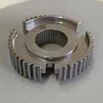
Deburring and grinding process of synchronizer hub of automobile transmission
2025-03-21CAESES and FLOW-3D Coupling Optimization Case: Die Casting Model Optimization
Die casting is a metal casting process where molten metal is forced into a die cavity to generate a corresponding model. In this case study, the focus is on the shape optimization of die-cast parts. A parametric model was created in CAESES software using 8 design variables, and the defined target parameters were calculated and monitored in conjunction with FLOW-3D software.
The main goal of this study was to reduce the amount of air entrained in the die casting process. At the same time, the free surface defect concentration (these surface impurities are mainly oxides on the free surface) was controlled to be no higher than the baseline model. A fully automated workflow based on CAESES and FLOW-3D was established, where CAESES optimization strategies were used to generate and analyze different design variants.
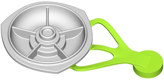
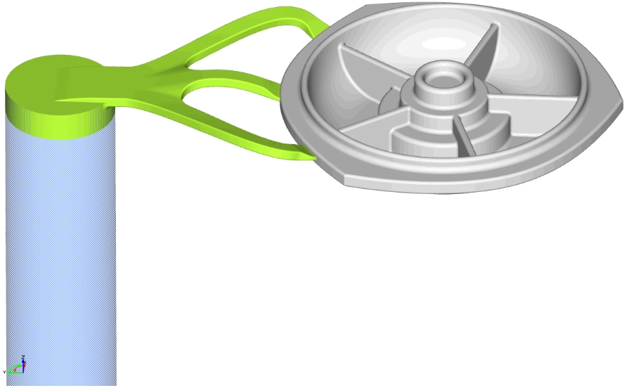
Casting system where the green part is shape-modifiable during the optimization process
Geometry Model
The initial reference geometry model is imported from outside and rebuilt into a fully parametric geometry model in CAESES. The mold, runners and injection sleeve areas are removed from a solid model to form a closed fluid domain model, and an automated workflow is established to automatically generate the mesh.
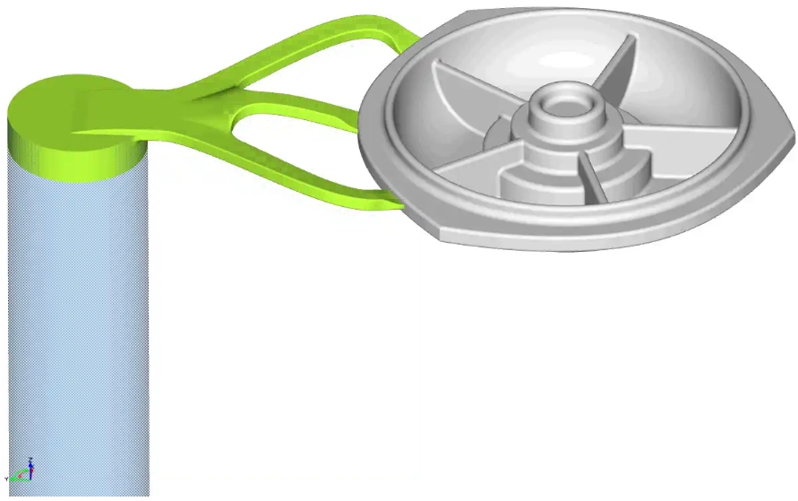
The length, angle and other geometric features of the part can be changed. The following animation shows some typical changes in the geometry model during automatic optimization:

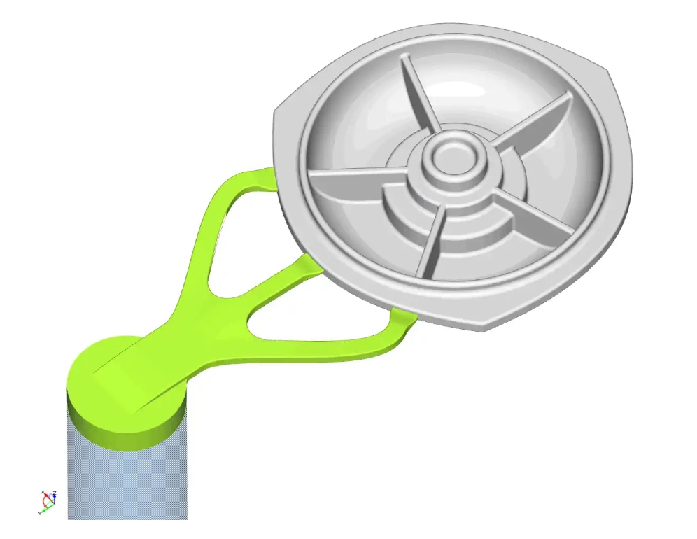
Constraints
The speed of the die casting liquid entering the die casting from the runner ranges from 20 to 60 m/s; this section model should be able to match the entire runner model; when the die casting liquid enters the die casting, it can enter the rapid pouring stage; the flow of the die casting liquid should pass through the shortest path from the thin section to the thick section.
Automatic CFD calculation
For the initial model, the analysis settings are made in the FLOW-3D software, and then these settings can be reused for the newly generated variants through the "software link" function in CAESES. Everything from material properties to mesh parameters can be controlled in CAESES. The result data generated by FLOW-3D can be automatically imported into CAESES and the target parameters can be extracted to evaluate the simulation results.
Mesh characteristics
The entire model mesh consists of two parts of non-completely matched meshes; the actual total number of meshes is about 1,400,000, and the basic mesh size is 2 mm.
Simulation characteristics
For the piston, its material is beryllium cobalt copper alloy (copper mold), the thermal conductivity is 300 (W/(m·K)), and the specific heat capacity is 3.52e+06 (J/(m³.K)). For the mold space, its material is iron l H13, the thermal conductivity is 28.6 (W/(m·K)), the specific heat capacity is 35618.014 (J/(m³.K)), and the maximum heat penetration depth is 14mm.
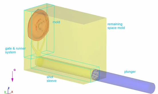
Overall setting of each component of die casting
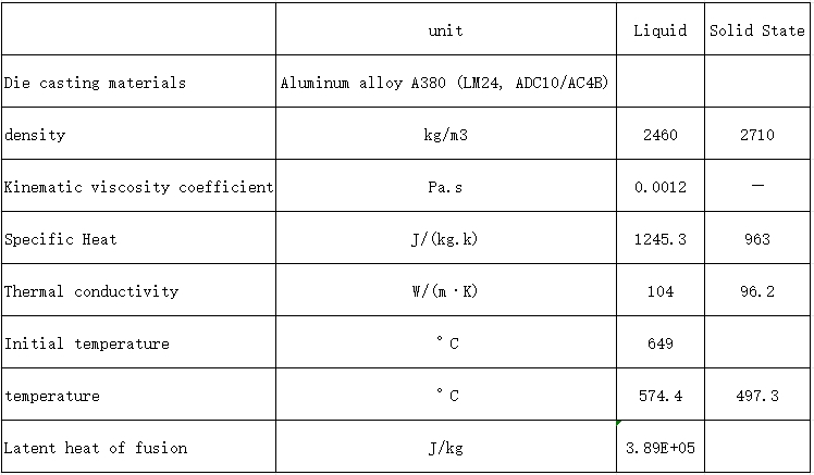
The characteristics of die casting liquid are shown in the following table:
Use a fluid with a free surface model and apply the following models:
• Air entrainment
• Cavitation
• Defect tracking
• Density evaluation
• Gravity and non-inertial reference frames
• Heat transfer
• Moving and simple deforming objects
• Solidification
• Viscosity and turbulence
Simulation results
The optimization process is divided into two stages. In the first stage, the basic flow parameters are optimized. In the fast pouring stage, the speed is controlled at 1.5~2.5m/s (the benchmark is 1.6 m/s). At the same time, the temperature of the die-casting liquid varies between 620℃~680℃ (the benchmark is 649℃).
After this stage of optimization, the second stage of simulation is carried out. In this stage, the shape parameter changes are controlled by the automatic optimization algorithm.
The overall optimization results show that the amount of entrained air is reduced by 15% compared to the initial baseline design; at the same time, the degree of free surface defects is reduced by 1%. It should be noted that the degree of free surface defects is not one of the target parameters of this optimization. The following pictures show some of the results of this study:
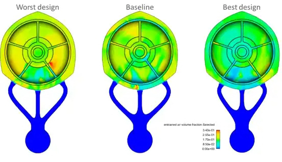
Comparison of entrained air volume
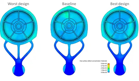
Comparison of free surface defect levels