


HXC Industrial Robot Die Casting Case
2025-03-22Analysis and Countermeasures of Typical Early Failure Cases of Aluminum Alloy High-Pressure Die Casting Dies
The failure of die-casting dies shortens the life of the dies, which not only increases the cost of the products, but also seriously affects the production, becoming a key problem that needs to be solved urgently in production. This article analyzes and discusses typical early die failure cases of aluminum alloy high-pressure die-casting dies during use. Case studies of common failure mechanisms of dies, namely cracking, thermal fatigue cracks, melting, cavitation, and deformation, are analyzed and technical solutions are pointed out.
"Cavitation" on the mold surface - mold design issues
"Cavitation" phenomenon: "pitting" is formed on the surface of the die-cast product.
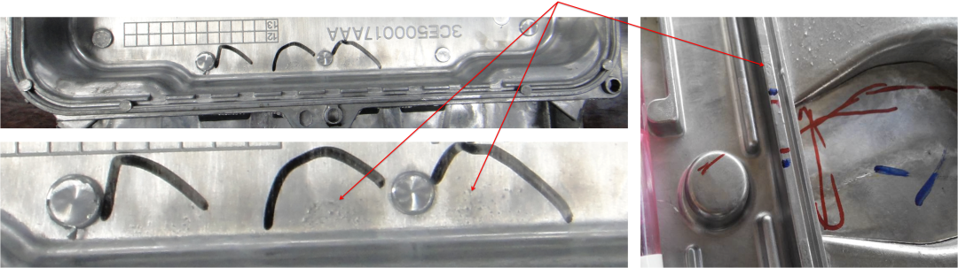
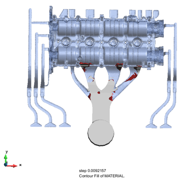
Cavitation occurs when the cross-sectional area of the runner path expands, which causes the pressure of the aluminum alloy liquid to drop during the flow of the runner, forming negative pressure cavities inside the liquid aluminum alloy. During the die-casting process and the pressurization stage, the negative pressure "bubbles" explode on the mold surface, damaging the mold material and causing the formation of "pitting". The formation of defects can be 200-300 molds.
Cause of cavitation: Expansion of runner cross-sectional area
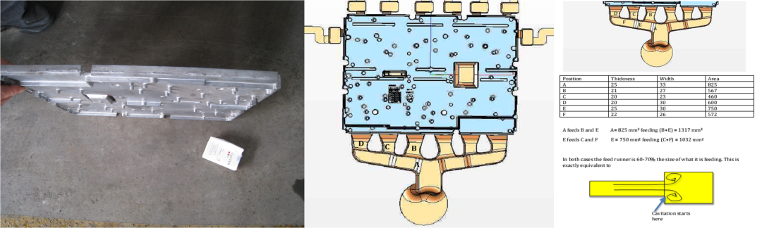
In the figure above, the cross-sectional area of the main runner on the side is A=825mm²; it branches into two branch runners B and E, and the cross-sectional area of the runner B+E is 1317mm²; in this way, the pressure of the liquid aluminum alloy drops during the flow of the runner, and a negative pressure cavity is formed inside it. The branch runner E further branches into C+F; the cross-sectional area of E is: 750mm²; the cross-sectional area of C+F is: 1032mm²; the pressure of the liquid aluminum alloy drops further, and a negative pressure cavity is generated inside it.
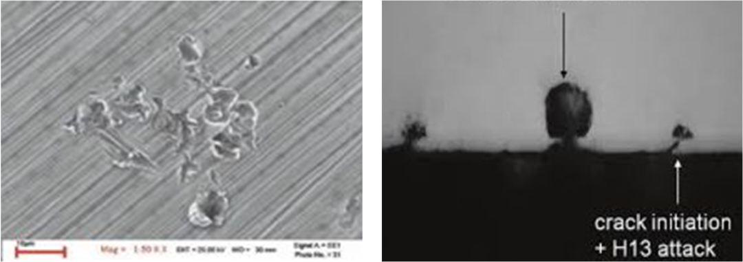
"Cavitation": Microscopic Analysis and Solutions
Mold design principles
New mold design basic principles:
1. Starting from the biscuit, the cross-sectional area of the main runner is in a compressed state in the path leading to the inner gate.
2. The R of the turn is more than twice the width of the cross section.
3. Gate shape: fan gate, tapered tangent gate, chisel gate.
4. Follow the definition of gate size.
5. Any ejector is parallel to the mold surface and cannot protrude or recess.
Mold erosion - the impact of injection speed and mold design
"Dissolution" phenomenon: the mold has less meat and is "worn away" partially. The product has more meat, the product shape changes, and ejection problems occur.
Solidified aluminum alloy blocks part of the gate
Early thermal fatigue - the effect of temperature difference
Mold thermal fatigue phenomenon: micro cracks form on the mold surface, which expand and cause the mold to fall off. The casting cannot be ejected.
A large die-casting mold (3500 tons) produced 3200 products, and a large number of thermal fatigue cracks formed on the mold surface near the gate, causing the product to "stick to the mold".
Note: If there is a problem with the toughness of the mold material, there should be cracks at the R corner of the boss.
Causes of mold thermal fatigue: The temperature difference on the mold surface affects the material's resistance to thermal fatigue.
The problem of early mold failure: mold cracking - temperature field considerations for mold design
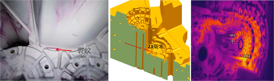
The above example shows the mold of a 3,000-ton die-casting equipment, with the cooling water 23mm away from the mold surface. Infrared imaging test shows that the mold surface temperature varies from 275°C/169°C/120°C. There are several reasons for the cracks: 1. The internal cooling water channel is 23mm away from the surface. 2. The mold cracks at the R angle of the step, with a large thickness variation. 110mm to 280mm. The residual stress of heat treatment is concentrated. 3. The groove of the triangular insert is produced by electrical discharge machining. It is recommended to process it before heat treatment so that the stress distribution will be along the mold shape, and the cooling water channel needs to be calculated.
Calculation of cooling water channel
Take aluminum alloy A383 as an example, its specific heat is: 2.90 J/cm³/℃, and its heat capacity is: 1094 J/cm³.
If we consider that 1 cubic centimeter of aluminum alloy is cooled from a liquid state at 593℃ to a solid state at 450℃ when the casting is ejected, the heat dissipated is: heat dissipated per cubic centimeter of aluminum alloy = specific heat + 2.90X (liquidus temperature - product ejection temperature)
=1094+2.90X (593-450)
=1500 (J/cm³)
If we consider 50 cubic centimeters of aluminum alloy, the heat dissipated from solidification to ejection is:
=50cm³X1500J/cm³
=75 (KJ)
If we consider 50 cubic centimeters of aluminum alloy, the shift output is 200 pieces/h; then, the shift output needs to be determined in the mold temperature field design step. At this time, the heat power emitted by the aluminum alloy is 75KJX200 pieces/h=15000(KJ/h).
If the moving mold and the fixed mold each take away 50% of the heat, then the heat power emitted by the mold in the moving mold is: 7500 KJ/h.
If the cooling water flow rate is 6L/min and a 6mm diameter water channel is used, the heat removed is 400KJ/h. The required cooling water channel length is: 7500/400=18cm. If the cooling water flow rate remains unchanged and a 10mm diameter cooling water channel is used, the water channel length is: 13cm.
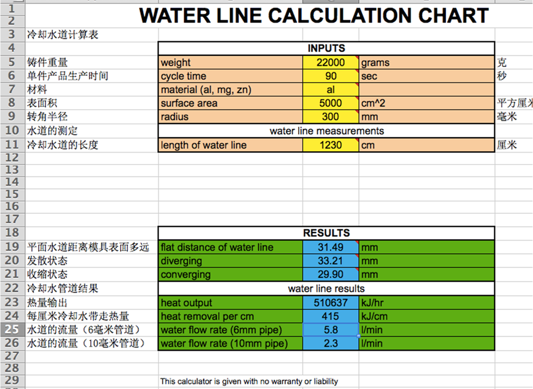
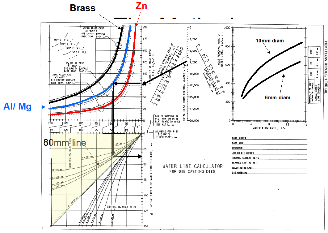
The Excel is a cooling water channel calculation table
Take the cylinder mold as an example:
Weight of casting product: 22 KG
Die casting cycle time: 90 s
Die casting alloy: aluminum alloy
Casting surface area: 5000 cm²
The calculated total cooling water channel length is: 1230 cm;
Cooling water distance from the surface: 29.9 mm-33.2 mm
Heat output: 510637 KJ/h
Heat taken away by cooling water channel per centimeter length: 415 KJ/h
Cooling water flow (6mm aperture): 5.8 L/min
Cooling water flow (10mm aperture): 2.3 L/min
The above is the total cooling water channel length. In the process of temperature field design, the casting needs to be decomposed. According to the wall thickness and the surface area of the mold in contact, the distance of the cooling water channel of a certain decomposed part from the mold surface, the water flow, and the aperture of the water channel are calculated.
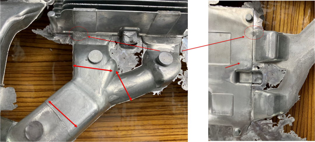
Even if the mold material and heat treatment have good process and quality control, there will still be problems with the mold. The reason is that the temperature field of many molds is not calculated. How close is the cooling water to the surface? This is especially true for spot-cooled molds.
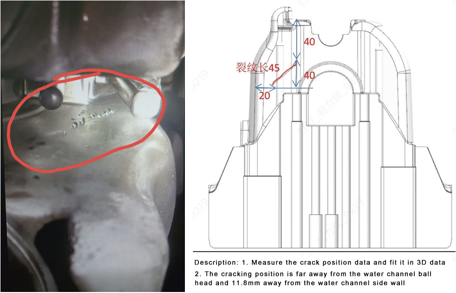
The picture shows that the mold insert on the crankshaft sleeve side of the cylinder mold has cracks on the side, causing the mold insert to leak. The leaking part is basically at the same level as the liquid level of the liquid aluminum alloy pre-filled (about 15%). This means that the water inside the cooling water pipe boils, causing the volume of the water to expand, and then the mold is cracked and leaks. The cooling water channel is 11.8mm away from the surface. Recommendation: The cooling water channel should be more than 15mm away from the mold surface to avoid mold cracking.
Deformation of mold - Consideration of dimensional expansion
Calculation of material expansion: expansion = material thermal expansion coefficient x temperature difference x 450. For large molds, it is especially important to consider that the mold is used at high temperature rather than room temperature. If the temperature difference between the surface and the back of a 635-length x 150-thick mold is 95°C, the arc of the mold surface is 0.5mm, and the sum of both sides is 1mm. Considering these variables can avoid local cracking of the mold, flash of die casting, and mold deformation.
Definition of R angle size, release agent spraying is part of the temperature field
The size of the product's R angle has always been one of the factors affecting the life of the mold. For most products, the R angle should be controlled to be above 1.5mm.
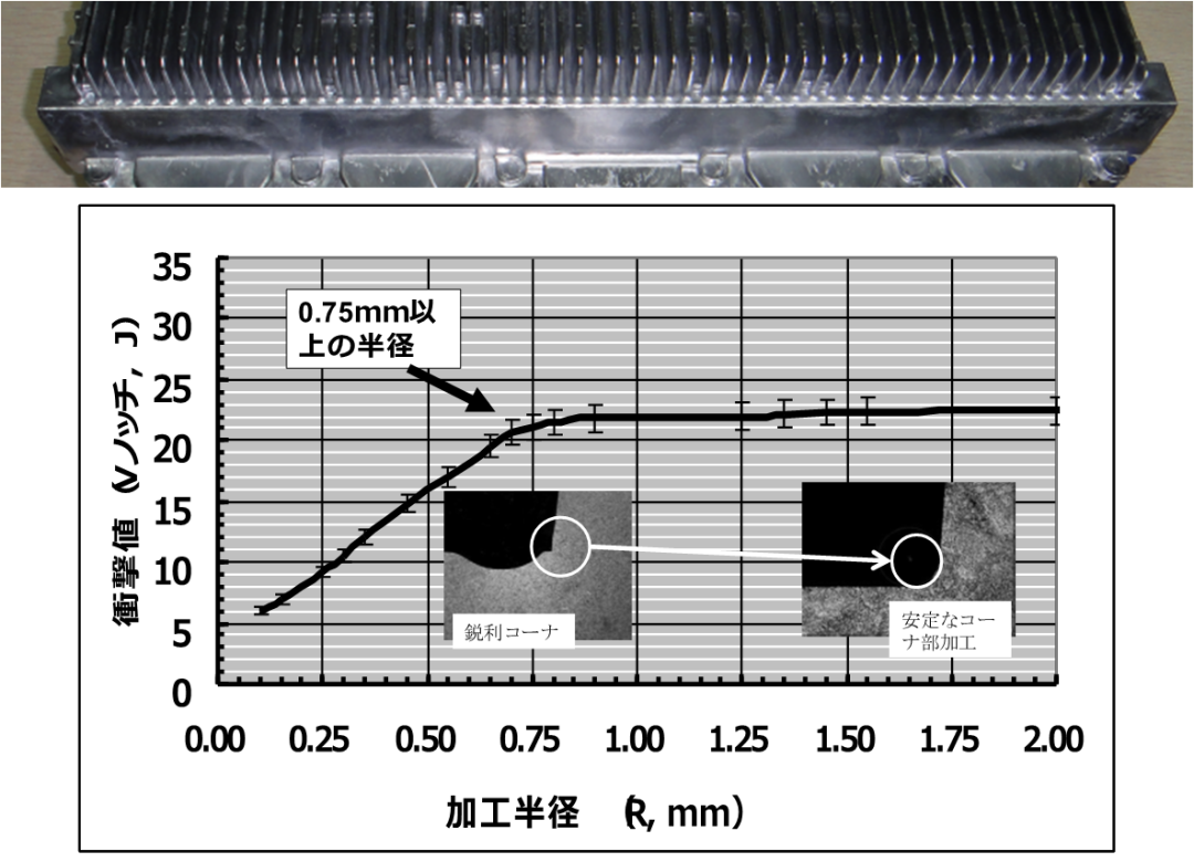
As shown in the figure, the R angle of the communication die-casting base station housing product is 90 degrees. The mold cracked after producing 1,000 products. When the R angle of the mold material decreases from 1.5mm to 0.5mm, the impact toughness of the mold material decreases from 22J to 16J. If R decreases to 0.25mm, the toughness of the mold material decreases to 8J. Since the die-casting mold is produced at high temperature, it is recommended that the R angle of the mold cavity be controlled above 2.5mm. Note: There should be no additional knife marks on the R angle part.
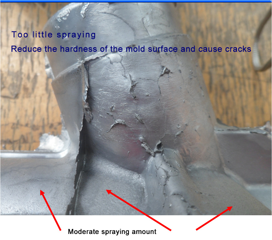
The spraying of water-based release agent will affect the life of the mold. After the mold shown in the figure produced 60,000 products, the thick wall of the casting product had serious thermal fatigue cracks. However, there were no thermal fatigue cracks in the thin wall. It is necessary to consider the local water-based release agent spraying amount, spraying angle, and calculate the heat taken away by the release agent. 1cm³ of water-based release agent can take away 2600J of heat. If the heat from 1cm³ of aluminum alloy from liquid to solidification is taken away by the spraying of release agent, then the required release agent spraying amount is 0.7cm³. Specifically, the release agent spraying amount needs to be calculated according to the shape of the product.
in conclusion
1. The formation of "pitting" on the mold surface caused by cavitation on the mold surface is a mold design problem. As long as the die-casting mold runner design principles are strictly followed, the entire cross-sectional area of the main runner from the material cake to the inner gate is in a contracted state, and the cavitation problem can be solved.
2. The problem of local dissolution of the mold inner gate is that the die-casting mold design principles are not followed when designing the mold runner. During the injection process, some aluminum alloy liquid reaches the inner gate first when flowing in the runner, and solidifies and blocks part of the gate, so that the subsequent aluminum alloy liquid reaches the inner gate. The local shooting speed is too high during the injection flow process, which leads to the dissolution of the mold gate. The solution to overcome this type of dissolution is to strictly follow the die-casting mold design guidelines to avoid the blockage of some pouring gates due to the pressure drop of liquid aluminum alloy during the flow of the runner.
3. The early thermal fatigue of the mold is mostly related to the temperature difference on the surface of the mold material. The article discusses the material stress and strain caused by the temperature difference. The conclusion of the case analysis is that the high temperature of the aluminum alloy liquid causes a large number of early thermal fatigue cracks on the mold surface after producing 3,200 products. The reason is that the aluminum alloy liquid temperature is abnormally higher than the tempering temperature of the mold material and reaches 630°C, which makes the hardness of the mold and the aluminum alloy liquid contact part decrease, and early thermal fatigue cracks appear.
4. There are many reasons for mold cracking. This article discusses the mold cracking phenomenon caused by the mold temperature field. For the specific temperature field calculation, it is necessary to calculate the design of the cooling water channel according to the excel table cited in the article. The cooling water channel is at least 20mm away from the mold surface, and the spot cooling distance is 15mm, so that the mold will not crack.
5. The deformation of the mold is due to the mold being produced at high temperature, so the mold material itself will expand, both the linear size changes and the shape of the surface protrusions. Considering these variables can solve the flash problem and deformation problem.
6. The size of the R angle is very important. The mold can begin to crack at the R angle after 1,000 molds. The recommended R value is R greater than 2.5mm. Release agent spraying is part of the mold temperature field. The specific spraying amount needs to be calculated to measure and control the spraying amount, only in this way can the goal of extending the service life of the mold be achieved.