


Efficient Deburring and Grinding Method for Die-cast Aluminum Auto Parts
2025-03-19
Machining Case of the Whole HXC Unmanned Aerial Vehicle (UAV)
2025-03-20GM applies FLOW-3D: Development of contact casting ladles for automobile cylinder heads
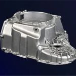
The cylinder head is made of cast iron or aluminum alloy. It is the mounting body of the valve structure and the sealing cover of the cylinder. The cylinder head bears the mechanical load caused by gas force and tightening the cylinder head bolts. It also bears high thermal load due to contact with high-temperature combustion gas, so the quality requirements for the product are quite high.
Since most cylinder heads are formed by casting, the common defects of castings have also become the focus of cylinder head quality assessment. The most common defects are subsurface pores and oxide film.
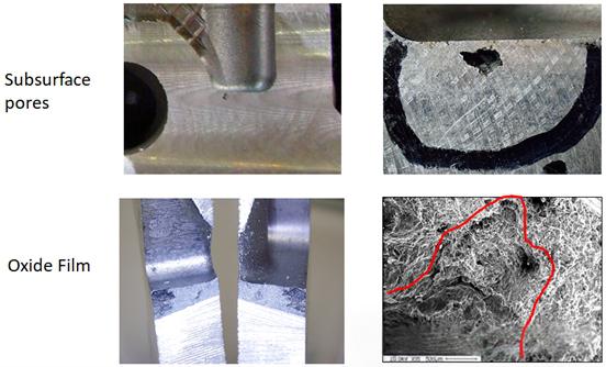
Picture 1. Common casting defects of cylinder heads
Tilt casting process description
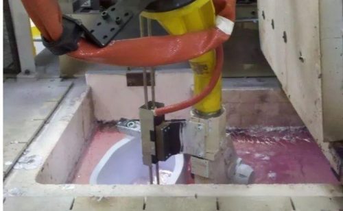
Image 2. Traditional tilt casting process
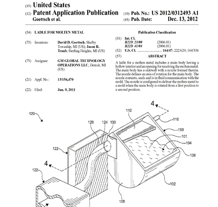
Image 3. Tilt casting patent
FLOW-3D CAST numerical simulation
Before numerical simulation, relevant meshes must be established and analysis parameters must be obtained.
The simulation model was established using Siemens NX, and simplified and 3D graphs were adjusted. FLOW-3D CAST was used for analysis.
FLOW-3D CAST uses four mesh blocks for analysis (mesh size 1.5-5mm). In order to obtain the flow rate and time parameters of air entrainment and oxidation inclusion, baffles are set at the runner and gate positions. The mold surface roughness is set to 0.1-0.3mm.
Figure 4 is the 3D graph of the analysis, and Figure 5 is the mesh establishment. Figure 6 is the rotation angular velocity setting for tilting.
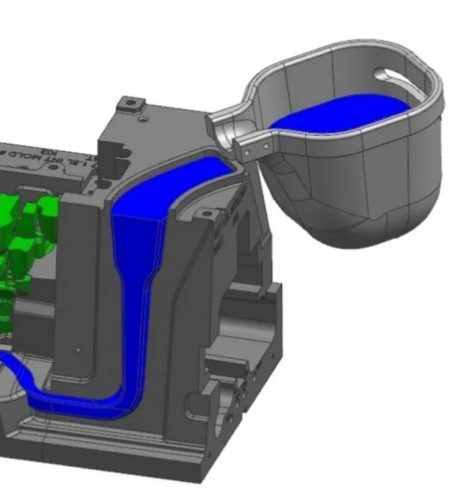
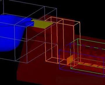
Figure 4. Three-dimensional diagram used in numerical simulation
Picture 5. Image imported from the actual mold
and FLOW-3D CAST grid establishment
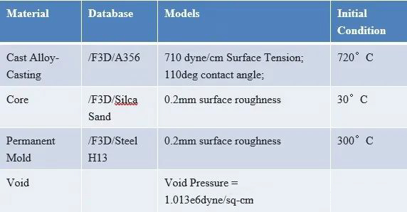
Table 1. Material library and pouring temperature

Table 2. Material Convection Heat Transfer Coefficients
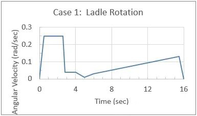
Figure 6. Case 1: Angular velocity of the watering pot rotation
During the rotation process, the original design would cause air entrainment due to turbulence at the flow channel bends, which could result in poor castings.
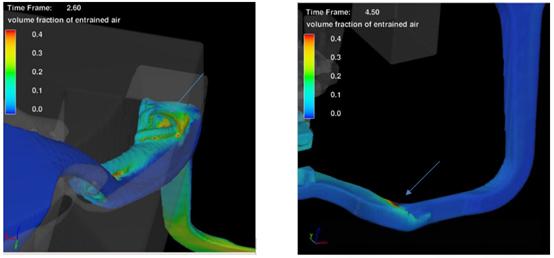
Figure 7. Metal turbulence during rotation causes air entrainment
According to the numerical simulation results, the overall filling time is about 14 seconds, and the maximum flow rate through the gate is 1.56Kg/s. The total amount of entrained gas is 250cc (about 3% of the metal volume). The entrained gas lasts for about 3.8 seconds.
Design Changes
According to the results of numerical analysis, during the rotation process, the molten metal will cause air entrainment in the runner due to turbulent impact. In order to improve this problem, the simplest way is to modify the runner shape and change the rotation speed.
According to the FLOW-3D CAST analysis results, multiple groups of runner design changes and rotation speed adjustments were made, and FLOW-3D CAST was used for simulation comparison.
Figure 8 shows the rotation angular velocity setting of the newly designed mold
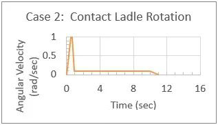
Figure 8. New mold rotation angular velocity
Figure 9 shows the filling process after the improved flow channel design.