


Art Lighting Solutions
2025-03-06
Case Study of Shrinkage Porosity in Ductile Iron Castings
2025-03-11Bubble tracking in gravity casting gating system
HXC's clients come from various industries around the globe. We understand the importance of an international mindset, integrity, sincerity, and a no-excuse attitude. It is this service mentality that is key to maintaining long-term cooperation with our clients. We take responsibility and treat our clients' products as if they were our own business。
Our services encompass prototype manufacturing, CNC machining, mold making, injection molding, die casting, sheet metal fabrication and stamping, extrusion, product assembly, as well as a variety of surface treatment services.
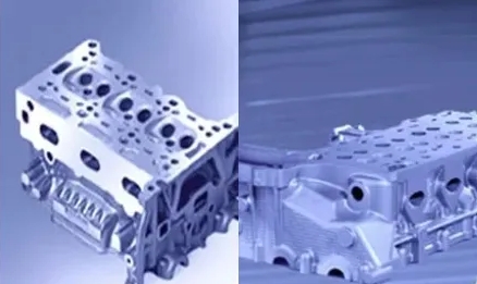
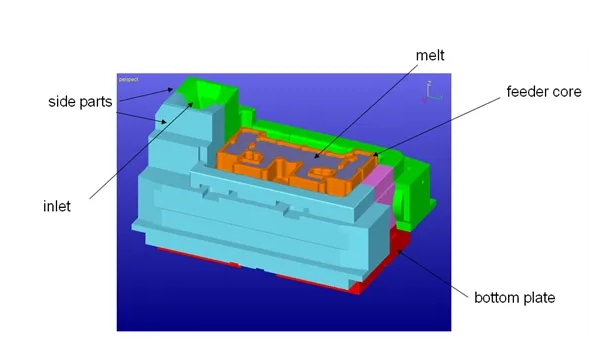
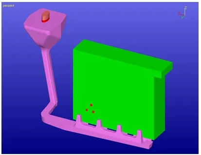
Mold body description
Casting system
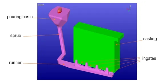
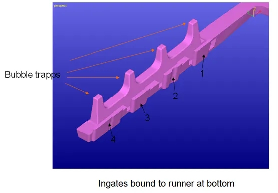
Gate design
The gate is connected to the casting by the bottom of the runner, and a bubble gathering area is designed in the middle of each gate.
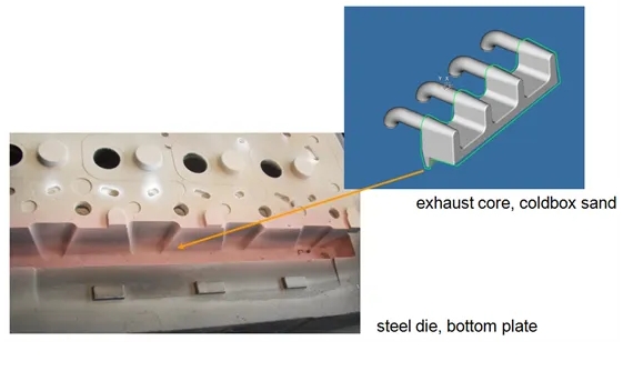
Description of the connection position of the mold body
Problem description
1. After the casting solidifies, shrinkage defects occur in the area between gate1 and gate2
2. I hope to use FLOW-3D CAST to understand the cause of shrinkage
Causes of shrinkage in castings
Review of the above four solutions to shrinkage cavities
- 1. Shrinkage holes
- 2. Consider shrinkage during solidification
- 3. Gas precipitation shrinkage
- 4. Allow the molten metal to release gas before pouring
- 5. Sand core gas leakage and shrinkage
- 6. Mainly from the gas generated by the adhesive
- 7. Most of the shrinkage cavities are evenly distributed
- 8. Air shrinkage
- 9. A low pressure zone occurs during the casting process, and gas is sucked in from the parting surface
- 10. Runner area
- 11. Gate area
- 12. Bubbles will continue to be generated during the pouring process
Cause confirmation
Analysis 1: Assume that the pressure change of the metal liquid during the pouring process brings gas into the casting
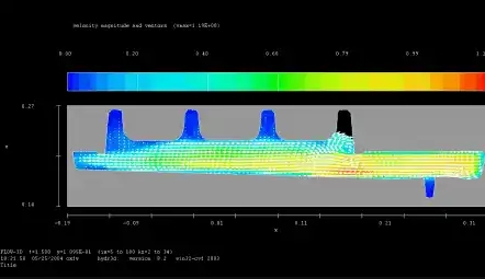
1. If the pressure at the runner and the gate is greater than the atmospheric pressure, it is impossible to suck gas from the parting surface.
2. If the flow rate at the gate position is the same, bubbles should be generated evenly at each gate position.
Flow velocity distribution in the gate area
Pressure changes in the runner system
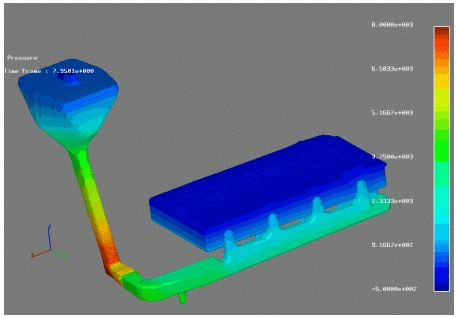
The results show that the pressure difference should not bring in gas.
Analysis 2: Assume that the molten metal brings gas into the casting in the runner during pouring
1. Gas existing in the sprue area
2. Will these gases be washed down to the runner area?
3. If these gases are washed down to the runner area and enter the gate, will these gases be concentrated in certain areas? Or are they evenly distributed?
4. Does the size of the bubbles affect the concentration?
5. Analysis simulation settings
6. Bubbles are generated at a uniform speed at the pouring cup position
7. Density: 10 times the density of air
8. Dimension design: 0.3 mm, 0.5 mm, 0.8 mm
9. Partial coupling (fluid movement will not be affected by bubbles)/full coupling (fluid movement will be affected by bubble movement)
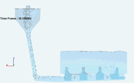
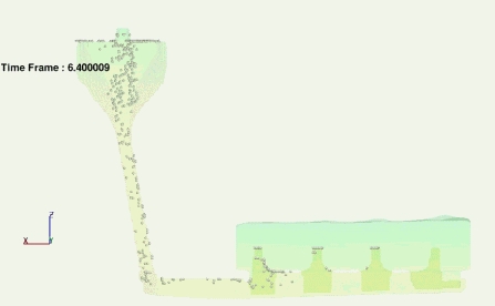
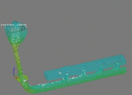
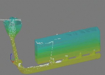
Open Bubble Simulation
- Bubbles generated below inlet with constant rate
- Density: 10 x density of air (oxide skin)
- Size (diameter): 0.3 mm, 0.5 mm, 0.8 mm
- Partial interaction/full interaction
Gate design A, bubble size 0.5mm, fully coupled.
Gate design A, bubble size 0.8 mm, fully coupled.
Gate design B, bubble size 0.3 mm, fully coupled.
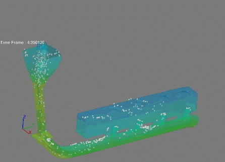
Gate design B, bubble size 0.5 mm, fully coupled.
Gate design B, bubble size 0.8 mm, fully coupled.
Conclusion
1. It was originally predicted that bubbles were defects generated during the casting solidification process.
2. Based on numerical simulation, the real cause of bubbles was confirmed.
3. The gating system can be optimized to reduce the problem of bubble generation.